

Clear electronics/RF guides, videos & downloads by Ian Poole | Resource hub for engineers & hobbyists | Shop: https://xitter.cf/t.co/ClrsfjiAbA
South East, England
Joined November 2016
- Tweets28.4K
- Following269
- Followers17.4K
- Likes2.5K





More information can be found in my website: electronics-notes.com/articl…
Understanding Varactor Diodes: what they are; how they work; where they are used
Have you ever wondered how your car radio "tunes" to a station or how your smartphone manages to jump between different frequency bands without a single moving part inside?
The secret lies in a component that combines the worlds of semiconductors and capacitors: The Varactor Diode (also known as the Varicap).
Based on insights from Electronics Notes, here is a look into how this "variable reactor" works and why it’s the key electronic component for modern wireless communication.
What is a Varactor Diode?
At its core, a Varactor is a semiconductor diode designed to take advantage of a phenomenon that most engineers try to minimize: Junction Capacitance.
While a standard diode is meant to conduct or block current, the Varactor is almost always operated in reverse bias. In this state, it doesn't conduct electricity; instead, it acts as a voltage-controlled capacitor.
How It Works:
To understand the Varactor, think of a traditional capacitor (two conductive plates separated by an insulator).
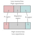
* The Depletion Region: When you reverse-bias a diode, an area empty of charge carriers (the depletion region) forms at the junction. This acts as our insulator.
* The P and N Layers: The conductive semiconductor material on either side acts as the capacitor plates.
* Capacitance Changes: As you increase the reverse voltage, the depletion region widens. In capacitor terms, this is like moving the plates further apart—which decreases the capacitance.
By simply changing the voltage, you change the capacitance. No knobs, no motors, just solid-state physics.
Abrupt vs. Hyperabrupt: The Doping Secret
Not all Varactors are created equal. The way the semiconductor is "doped" during manufacturing changes how it responds to voltage:
* Abrupt Varactors: Have a constant doping level. They offer a linear relationship and a high "Q" (quality factor), making them great for high-frequency precision.
* Hyperabrupt Varactors: Have a non-uniform doping profile that creates a much larger change in capacitance for a small change in voltage. These are the workhorses of wide-band tuning.
Where Do We Use Them?
Without the Varactor, our modern "connected" world would look very different. They are essential for:
✅ Voltage Controlled Oscillators (VCOs): The heart of frequency synthesizers and Phase Locked Loops (PLLs).
✅ RF Filters: Allowing devices to "track" a signal and filter out interference dynamically.
✅ Frequency Modulators: Directly shifting the frequency of a signal to carry information (FM radio).
Pro Tip for Designers
When using a Varactor, the "Capacitance Ratio" is your most important metric. It tells you the range between the minimum and maximum capacitance the diode can achieve. If you need a wide tuning range, go Hyperabrupt; if you need low loss at high frequencies, stick with Abrupt.
Have you ever had to troubleshoot a VCO or a tuning circuit? What’s your go-to Varactor for RF projects?👇
I’ve dropped the link to the full technical guide from Electronics Notes in the comments
#Electronics #RFEngineering #WirelessTechnology #CircuitDesign #RFdesign #HardwareEngineering #Varactor #Semiconductors #electroniccomponents

ElectronicsNotes by Ian Poole retweeted
The Iconic 2N3055 Power Transistor: the device that changed electronics.
There is a fascinating story behind this iconic power transistor. Not only was it revolutionary when it was introduced, but it has remained a go-to for many applications even to this day - over 60 years after it was launched.
The device is rugged, capable of handling serious power, it is widely available and cheap - what more could you want.
In my video I not only look at its history, but more importantly I look at its performance, its applications, and some points to watch out for as well as a surprising application.
Find out everything, watch my video now: youtu.be/AlKwDjhUxj8
#2N3055 #transistor #semiconductor #electroniccomponents #electronicsnotes
ElectronicsNotes by Ian Poole retweeted
How do you keep your DMM probe on the test point while you are away at looking at the display.
As you look away, it's so easy for the probe you are holding to slip.
Instead is so much easier to use a Pen style DMM like the ANENG A3008 that you see here.
(Sponsored link)
Check out more - its low cost and great performance: link.amazon/B06T6VkAG
#DMM #digitalmultimeter #ANENG #ANENGA3008
🤝 Paid partnership
Check out this excellent breakdown on Electronics-Notes: electronics-notes.com/articl…
Linear Power Supplies need a Reservoir Capacitor - Here’s Why!
The smoothing capacitor is used to convert the raw rectified AC into the smooth DC required by sensitive electronics. The capacitance and period the smoothing capacitor are crucial.
In both linear and switch-mode power supplies, the rectifier output consists of a series of half-sine waves.
Without smoothing, digital circuits would lose power every half-cycle, and analogue circuits would be plagued by hum and noise.
Here are 3 key takeaways for engineers and hobbyists on getting smoothing right:
1️⃣ The "Fill in the Gaps" Strategy:
A reservoir capacitor (typically an aluminum electrolytic) works by charging up at the voltage peak and discharging into the load when the rectifier voltage drops. Essentially, it "fills in the dips" to maintain a steady output.
2️⃣ Full-Wave vs. Half-Wave:
Efficiency matters! Full-wave rectification is always preferable because the gaps between peaks are shorter. This leads to significantly better smoothing and allows for a smaller capacitor to achieve the same ripple voltage.
3️⃣ Don't ignore Ripple Current!
When choosing a capacitor, capacitance and voltage aren't the only specs that matter. You must check the Maximum Ripple Current.
* Because the capacitor only charges during a very short window of the cycle, the peak charging current can be much higher than the steady-state load current.
* Overlooking this leads to overheating, reduced lifespan, or even catastrophic failure.
Pro-tip for the maths: To estimate peak-to-peak ripple Vripple for a full-wave rectifier, use:
👉 Vripple = Iload / (2 f C)
Looking to go deeper into the calculations and filters? Check out the link in the comments.
#ElectronicsEngineering #PowerSupply #circuitdesign #HardwareDesign #electronicsnotes #electroniccomponents #LearningElectronics

Check out the full guide on Electronics Notes: electronics-notes.com/articl…